7 Essential Circuit Symbols and Their Functions Revealed

The World of Electrical Engineering: Unpacking Circuit Symbols

Entering the vast domain of electrical engineering, one encounters a language that transcends traditional verbal communication, focusing instead on visual symbols known as circuit symbols or schematic symbols. These symbols are the lexicon of electrical and electronic engineers, used universally to design, analyze, and troubleshoot circuits. Here, we dive into seven essential circuit symbols that are fundamental to understanding and working with electrical circuits.
1. Resistor Symbol


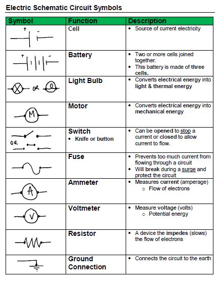
A resistor, as implied by its name, resists the flow of electric current, thereby creating a voltage drop across itself. Its circuit symbol resembles a jagged line, symbolizing the opposition to current:
- Symbol: A zigzag line or series of rectangles to represent the material opposing electron flow.
- Function: To control current, protect components, and adjust signal levels.
🔌 Note: The resistance value is given in Ohms (Ω), and different colors on the physical component can indicate its resistance value.
2. Capacitor Symbol


Capacitors store and release electrical energy over time, used in timing circuits, filtering, and signal coupling. Their symbol illustrates two parallel plates:
- Symbol: Two parallel lines, often with one curved or angled, representing the plates.
- Function: To temporarily store energy, smooth out voltage fluctuations, or block DC current while allowing AC to pass.
3. Inductor Symbol


Inductors resist changes in current through self-induction, commonly used in filters and energy storage:
- Symbol: A series of curved or angled lines to represent wire windings.
- Function: To store energy in a magnetic field, smooth out current flow, or provide reactance in AC circuits.
4. Diode Symbol


Diodes allow current to flow in one direction only, acting as electronic check valves:
- Symbol: A triangle pointing towards a vertical line, with a bend arrow to show the direction of current flow.
- Function: To convert AC to DC (rectification), protect circuits, and regulate voltage.
5. Transistor Symbol


Transistors amplify or switch electronic signals and are fundamental to modern electronics:
- Symbol: For an NPN transistor, it looks like a pointed shape with three leads (Collector, Base, Emitter). For a PNP, the arrow points inward.
- Function: To amplify weak signals, control current flow, or serve as electronic switches.
6. Battery Symbol


Batteries provide a constant voltage source to circuits:
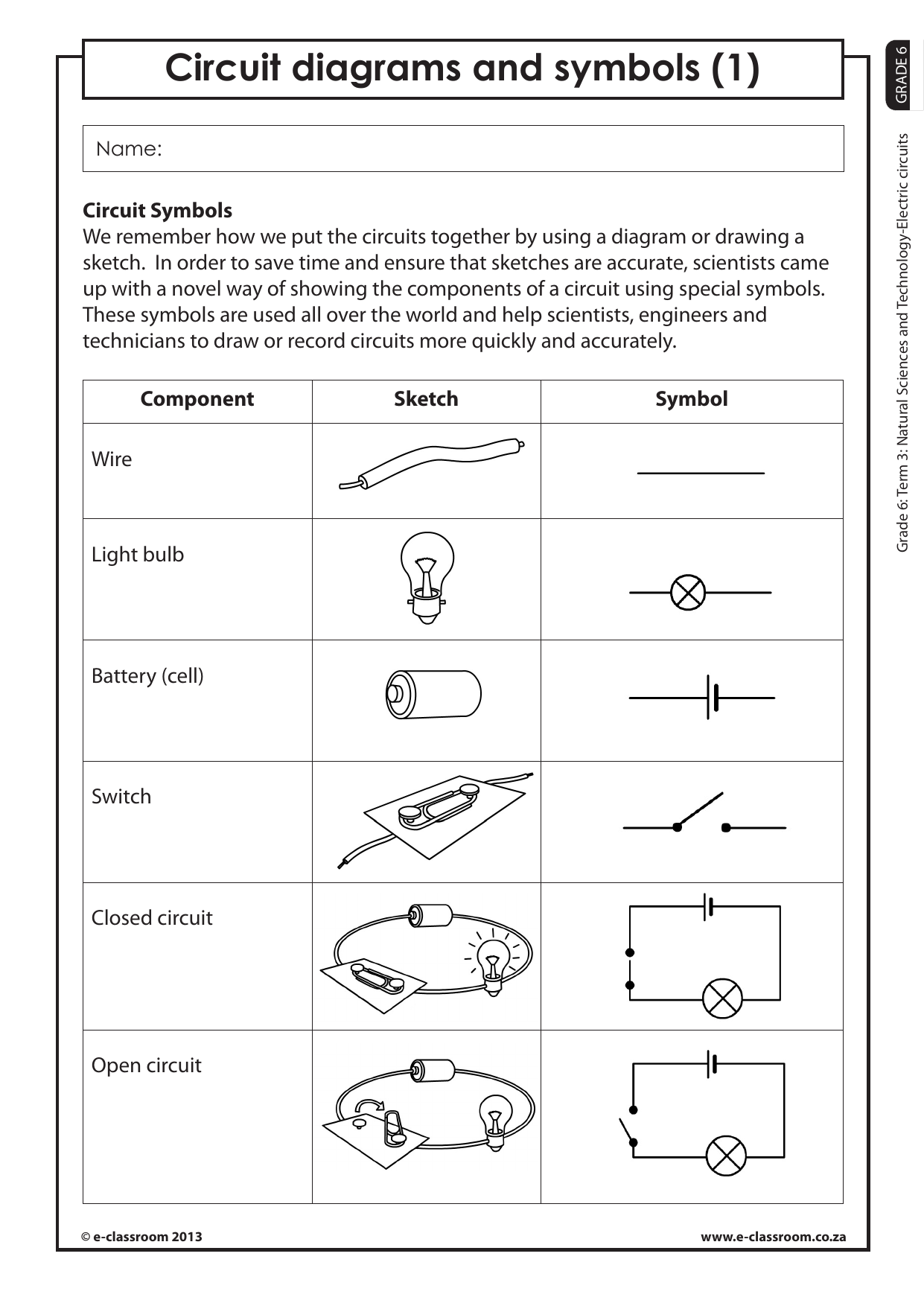
- Symbol: Two or more parallel lines to represent the cells, with a longer line indicating the positive terminal.
- Function: To supply electrical energy, maintaining a potential difference for circuit operation.
7. Ground Symbol


Grounding serves as a reference point for electrical circuits:
- Symbol: Three decreasing parallel lines or a vertical line with a flag on the end.
- Function: To provide a common reference point for voltage measurements, ensuring safety and protection from surges.
With this rich tapestry of symbols, electrical engineers can communicate complex ideas succinctly. Understanding these symbols unlocks the gateway to designing and troubleshooting circuits with precision. As circuits evolve, so too do their symbols, reflecting advancements in technology and the needs of circuit designers.
From controlling the flow of current with resistors to managing voltage levels with capacitors, these symbols are not mere representations but essential tools in the engineering process. They highlight the ingenuity of human invention, allowing for rapid communication and fostering innovation in electronic design. In summary, grasping these symbols not only aids in technical proficiency but also connects one with the essence of modern electronic engineering.
What’s the difference between NPN and PNP transistors?

+
The primary difference is in the doping of the transistor layers. In an NPN transistor, the outer layers are N-type, while the middle layer (base) is P-type. For PNP, it’s reversed. This configuration affects how the transistor controls current flow.
Can inductors and capacitors work together in a circuit?

+
Yes, inductors and capacitors often work in tandem to form LC circuits or oscillators, which can be used for frequency selection, tuning, and filtering.
Why do we need a ground symbol in circuit diagrams?

+
The ground symbol provides a reference point for all other voltages in the circuit, ensuring all measurements are relative to a common zero potential point, which is critical for accurate operation and safety.


