Series Circuit Worksheet: Master Electrical Basics Easily

Understanding electrical circuits forms the foundation of learning electronics, and it all starts with the basic building block: the series circuit. Whether you're an aspiring electrical engineer, a hobbyist in electronics, or a student grappling with the fundamentals, mastering series circuits will pave the way for more complex circuit designs. This comprehensive guide provides an engaging and structured approach to understanding and applying the principles of series circuits, making it easier for you to get a firm grasp on electrical basics.
What is a Series Circuit?

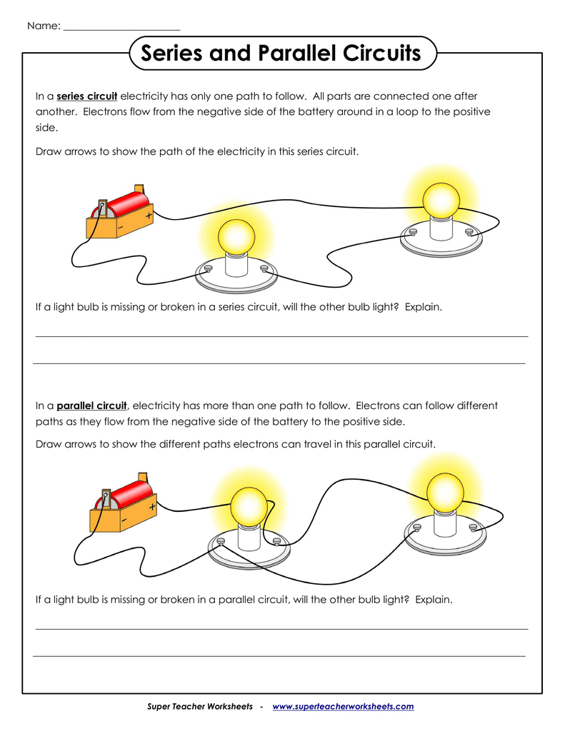
In its simplest form, a series circuit is a circuit in which components are connected end-to-end in a single pathway for electric current to flow. Here’s a quick breakdown:
- The same current flows through each component.
- The total voltage drop is the sum of the voltage drops across each component.
- The resistance or impedance of components adds up to give the total resistance or impedance of the circuit.
Essential Components in a Series Circuit

A series circuit typically includes:
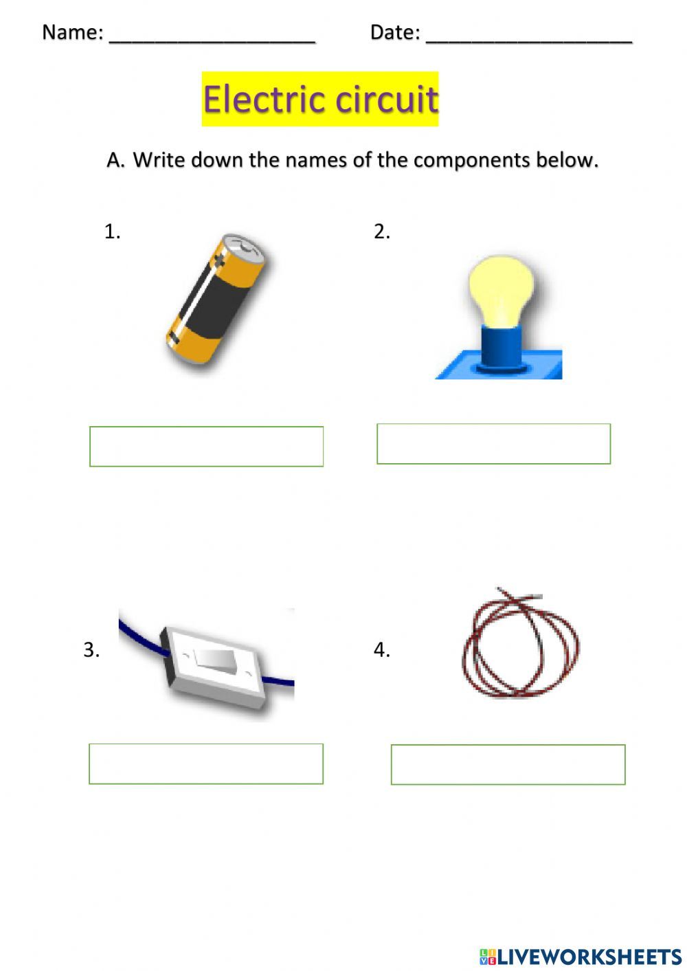
- Power Supply: This could be a battery, a generator, or any source of electrical power that provides the voltage.
- Loads: These are components that consume power, like resistors, lights, or electronic devices.
- Conductors: Wires that connect the components, allowing current to flow.

Key Laws Governing Series Circuits

To analyze and design series circuits, you need to understand the following laws:
Ohm’s Law

Ohm’s Law is fundamental in electrical engineering, stating:
- V = I * R (Voltage = Current * Resistance)
⚡ Note: Ohm's law is applicable only to linear circuits, and in series, the total resistance (R) is the sum of the individual resistances.
Kirchhoff’s Voltage Law (KVL)

This law states that the sum of all electric potential differences (voltage drops) around any closed circuit loop must equal zero. Mathematically:
- ∑V = 0 around any loop in the circuit.
Performing Calculations in Series Circuits

Here's how to calculate various aspects of a series circuit:
Total Voltage

The voltage drop across each component in series adds up to the total voltage applied by the power supply:
- V_total = V1 + V2 + V3 + ... + Vn
Total Resistance

In series circuits, the total resistance is simply the sum of the individual resistances:
- R_total = R1 + R2 + R3 + ... + Rn
Current

Since the current is the same through all components:
- I = I1 = I2 = I3 = ... = In
| Component | Voltage Drop (V) | Resistance (Ω) |
|---|---|---|
| Resistor 1 | 10V | 2Ω |
| Resistor 2 | 20V | 4Ω |
| Total | 30V | 6Ω |

🔍 Note: When you calculate the total voltage, ensure that you account for the polarity of the voltage drops; they should cancel out in a complete loop.
Example Calculation

Let's walk through an example:
- Resistor 1: R1 = 2Ω
- Resistor 2: R2 = 4Ω
- Total Voltage: V_total = 30V
Using Ohm's law and KVL:
- I = V_total / (R1 + R2) = 30V / 6Ω = 5A
- Voltage drop across R1: V1 = I * R1 = 5A * 2Ω = 10V
- Voltage drop across R2: V2 = I * R2 = 5A * 4Ω = 20V
These calculations show how the total voltage is distributed across the resistors in series, and the current remains constant throughout the circuit.
Troubleshooting Series Circuits

If a series circuit doesn't work as expected, consider these common issues:
- Open circuits: A break in the circuit path.
- Short circuits: A bypass that causes excessive current flow.
- Incorrect values or connections: Check resistances and connections.
🔧 Note: When troubleshooting, a multimeter is your best friend; use it to measure voltage, current, and resistance at various points in your circuit.
Applications of Series Circuits

Series circuits have practical applications in:
- LED lighting strips, where current must be consistent for uniform brightness.
- Protection devices like fuses or resettable fuses in a series for safeguarding circuits.
- Alarm circuits where a break in the wire will trigger an alarm.
Wrapping Up

Series circuits provide a fundamental understanding of how current, voltage, and resistance interact. By mastering these concepts, you set the stage for delving into more complex circuits like parallel or combination circuits. Remember that the essence of learning electronics is hands-on experience, so try to simulate or construct your own series circuits to see these principles in action. Whether you're building a basic project or diagnosing complex electrical problems, the insights gained from series circuit analysis will be invaluable in your electrical and electronics journey.
Why is it important to understand series circuits?

+
Series circuits are fundamental building blocks of all electrical systems. They allow you to understand current flow, voltage distribution, and how components interact within a single current path, which is essential for more complex circuit analysis and design.
What happens if one component in a series circuit fails?

+
If a component in a series circuit fails, typically by becoming an open circuit (break in the wire), the entire circuit fails because the current cannot flow through the break. This characteristic makes series circuits ideal for applications where failure needs to be obvious, like alarm systems.
Can I use Ohm’s Law in both series and parallel circuits?

+
Yes, Ohm’s Law (V = I * R) applies universally to linear circuits, regardless of the configuration. However, how you calculate total resistance ® differs between series (sum of resistances) and parallel circuits (inverse sum of resistances).


