5 Essential Circuit Symbols Every Engineer Must Know

Understanding circuit symbols is fundamental for anyone involved in electronics and electrical engineering. These symbols provide a universal language that allows engineers and designers to communicate complex circuit designs quickly and accurately. In this post, we'll delve into five essential circuit symbols that are critical for both beginners and seasoned professionals to understand.
1. Battery Symbol

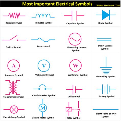
The battery is a primary source of electrical energy in many circuits. The circuit symbol for a battery represents a collection of cells connected in series to provide a higher voltage than a single cell could deliver alone:
- A battery is depicted as a series of long and short parallel lines.
- The longer lines represent the positive terminal, and the shorter lines signify the negative terminal.
- In some diagrams, the battery might be represented by one or more cells, but functionally, they represent the same concept.
Example in Circuit:


2. Resistor Symbol

A resistor is one of the most common components in electronic circuits, used to control current flow or to adjust signal levels. Here’s how it’s represented:
- The symbol for a resistor looks like a zigzag line, symbolizing the resistance to current flow.
- The zigzag can be vertical or horizontal, but the key is the representation of obstruction.
- Resistor symbols can also include additional markers to indicate variable resistors or potentiometers.
Example in Circuit:


⚠️ Note: Resistors can have different wattage ratings, which are often not indicated in schematic symbols. Always check the specifications when selecting components.
3. Capacitor Symbol

Capacitors store and release electrical energy. Here are the key points about capacitor symbols:
- Fixed Capacitor: Represented by two parallel lines with a gap between them or by a curved line (positive plate) facing a straight line.
- Variable Capacitor: Symbol includes an arrow to denote adjustability.
- Polarized Capacitor: Has a plus sign or a longer plate to indicate the positive lead.
Example in Circuit:


4. Inductor Symbol

Inductors are essential for applications like filtering, energy storage, and transformers. Their symbol reflects their function:
- The inductor symbol is a series of interconnected loops or a coil of wire.
- Some schematic diagrams may use straight lines or arcs to represent the coil.
- An arrow can be included to show a variable inductor.
Example in Circuit:


5. Diode Symbol

Diodes are semiconductor devices that allow current to flow in one direction only:
- The symbol is an arrow pointing in the direction of conventional current flow (from anode to cathode).
- The triangle shape also points in the direction of electron flow (from cathode to anode).
- There are variations like LEDs, Zener diodes, or Schottky diodes with slight modifications to the basic symbol.
Example in Circuit:


💡 Note: Not all diodes are the same; ensure you understand the specific type you're working with, as their properties can affect circuit behavior significantly.
In summary, mastering these circuit symbols is vital for effective communication in engineering projects. From batteries to diodes, each symbol represents a core component with distinct electrical properties. By understanding these symbols, engineers can design, analyze, and troubleshoot circuits with precision. Incorporating these symbols into your knowledge base will undoubtedly enhance your capabilities in electronics and electrical engineering, providing a foundational skill set for both professional and educational endeavors.
Why do we use symbols in circuit diagrams?

+
Circuit symbols allow engineers and designers to communicate complex circuits using a universal language. This standardization simplifies circuit design, documentation, and understanding across different cultures and languages.
Can a capacitor work as a battery?

+
While capacitors can store energy and provide it to a circuit, they cannot sustain a steady voltage like a battery due to their charge-discharge nature. However, supercapacitors are sometimes used for applications requiring short bursts of energy.
How do I know which way to connect a diode?

+
Diode symbols include an arrow that points in the direction of conventional current flow (anode to cathode). Always ensure the diode is connected according to this arrow for the circuit to function correctly.


