Series vs Parallel Circuits: 5 Key Differences Explained

Understanding how electricity works is fundamental in the world of electronics and engineering. Among the various concepts, the distinction between series and parallel circuits stands out due to its impact on circuit behavior. Whether you're a student learning the basics, an electronics hobbyist, or a professional, knowing the difference between series and parallel circuits can significantly influence your approach to design and troubleshooting. Let's delve into the key differences, their applications, and how each type affects electrical components.
1. Path of Current Flow


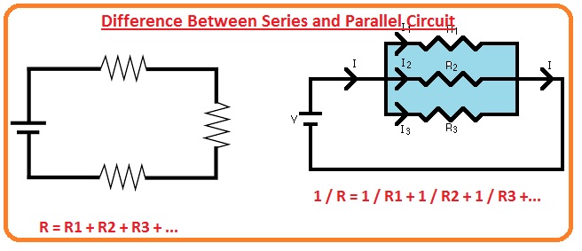
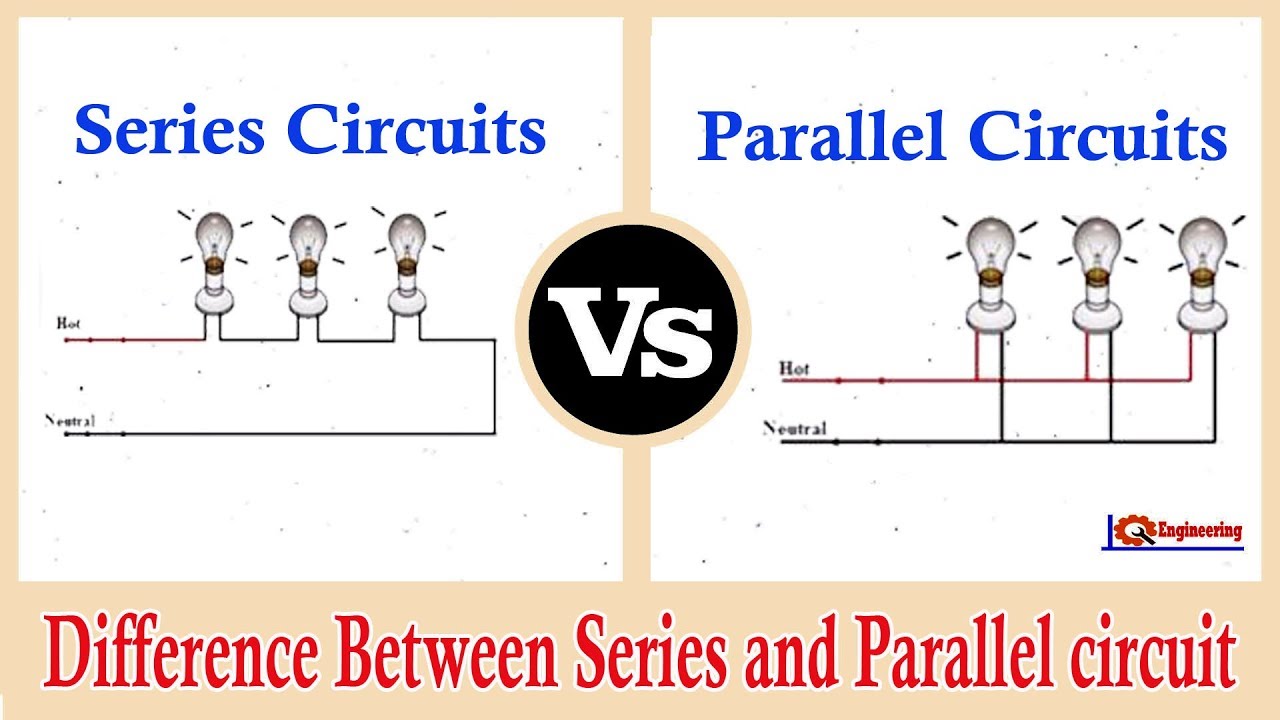
- Series Circuit: In a series circuit, components are connected end-to-end, forming a single path for current. The current flows through each component in order, meaning the current remains constant throughout the circuit. If one component fails or is disconnected, the entire circuit stops working.
- Parallel Circuit: Here, components are connected across the same two points, providing multiple paths for current flow. Each component has its own branch, and the current splits at each junction, with the total current being the sum of the currents through each branch. This setup ensures that if one component fails, others can still function independently.
2. Voltage Drop

| Circuit Type | Voltage Across Components |
|---|---|
| Series | The total supply voltage is divided among the components; each component experiences a voltage drop proportional to its resistance. |
| Parallel | The voltage across each component is the same and equal to the source voltage, regardless of their resistance or other characteristics. |

Understanding this can help in selecting the right type of circuit for your needs, especially when dealing with devices that require specific voltage levels.
3. Effect on Circuit Elements

- Resistance: In a series circuit, the total resistance is the sum of individual resistances (Rtotal = R1 + R2 + … + Rn), making the circuit less efficient as more components are added. In a parallel circuit, the total resistance is less than the smallest individual resistance (1/Rtotal = 1/R1 + 1/R2 + … + 1/Rn).
- Power Dissipation: Series circuits distribute power among components, while parallel circuits distribute it across multiple paths. This has implications on how heat is managed in electronic devices.
4. Reliability and Redundancy

- In a series circuit, reliability is lower because one failed component can disable the entire circuit. Conversely, parallel circuits offer higher reliability due to redundancy; if one component fails, current can still flow through other branches.
5. Applications and Use Cases

- Series Circuits: Ideal for scenarios where you want to control current flow or utilize voltage dividers. Examples include Christmas light strings where if one bulb fails, all go out; this is less critical in non-critical applications.
- Parallel Circuits: Preferred for lighting systems, electrical wiring in homes, and battery configurations where maintaining power is crucial. They are more practical in situations where you need to ensure multiple devices work independently.
⚠️ Note: Always ensure that the total power drawn by parallel devices does not exceed the capacity of your power source to avoid overloading or damaging equipment.
Throughout our exploration, we've seen how series and parallel circuits offer distinct electrical characteristics with unique advantages and applications. Series circuits are simpler in design and use when control over current and voltage distribution is needed, while parallel circuits are employed for redundancy, stability in voltage, and to ensure multiple devices operate independently. Understanding these differences not only enhances your ability to troubleshoot but also to innovate in electronic design. Remember, the choice between these circuit configurations depends on the requirements of the system you're working with, be it safety, efficiency, or performance.
Which circuit should I choose for a voltage regulator?

+
A series circuit might be more appropriate for a voltage regulator because it allows for precise control over voltage division. However, if you need to regulate multiple devices independently, a parallel configuration could also work.
Can I mix series and parallel configurations?

+
Yes, mixed or combination circuits can be designed to leverage the benefits of both configurations, often used in complex electronic systems.
How do I calculate current in parallel circuits?

+
Use Ohm’s Law in combination with parallel resistance formula. Total current is the sum of currents through each branch, where Itotal = I1 + I2 + … + In.