5 Ways to Master Parallel and Series Circuits

Understanding how electrical circuits work is fundamental for anyone interested in electronics, from students to seasoned engineers. Among the myriad of circuit configurations, parallel circuits and series circuits stand out due to their common usage and unique properties. In this comprehensive guide, we will explore five methods to master the art of circuit analysis, particularly focusing on these two circuit types.
Understanding Basic Circuit Theory

Before we delve into mastering parallel and series circuits, it’s crucial to have a grasp of the basics:
- Ohm’s Law: Voltage (V) equals current (I) times resistance ®. Expressed as V = IR.
- Kirchhoff’s Laws: These govern the conservation of electric charge and energy in a circuit.
- Resistor Color Code: Recognize resistor values using the color code system.
💡 Note: For beginners, using an Ohm’s Law calculator or referencing resistor charts can significantly aid in understanding.
An embedded image here can illustrate the circuit theory basics and the resistor color code chart.
Visualizing Circuit Diagrams

Creating and interpreting circuit diagrams is an essential skill for mastering electronics:
- Components Symbols: Learn standard symbols for resistors, capacitors, inductors, batteries, and more.
- Drawing Tools: Utilize software like Fritzing, Eagle, or even online tools for drawing circuits.
- Practical Diagrams: Transform theoretical circuits into practical layouts for prototyping.
Analyzing Series Circuits

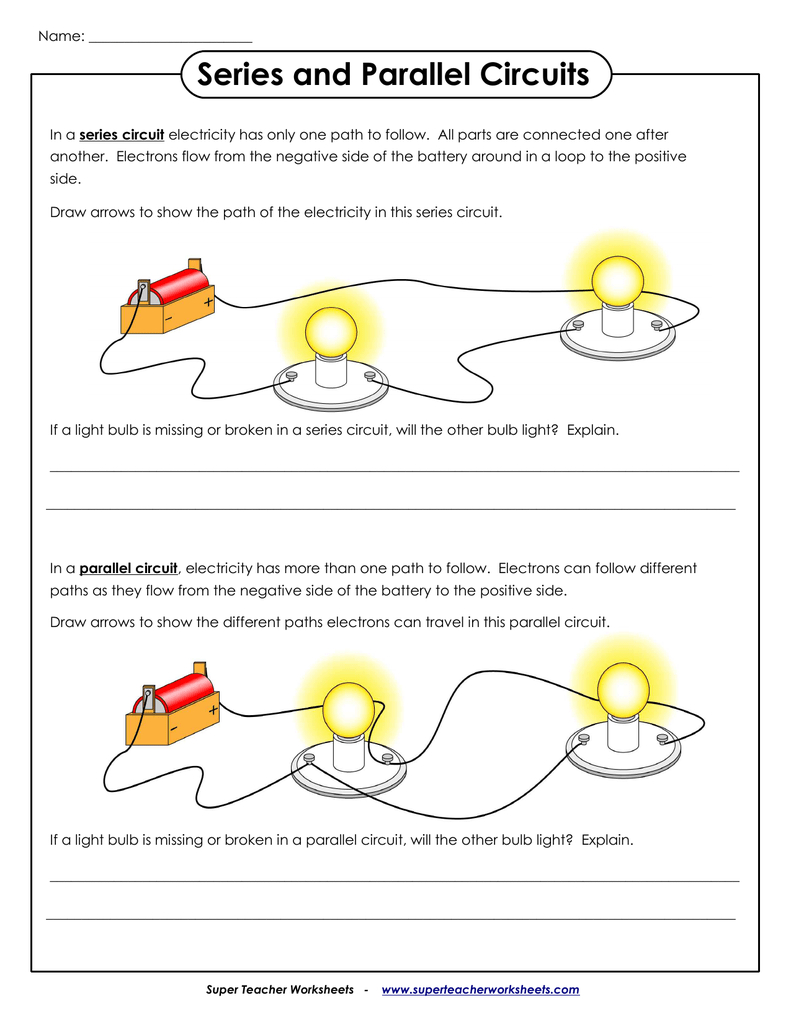
Series circuits are simpler to understand due to their linear flow. Here are some key points:
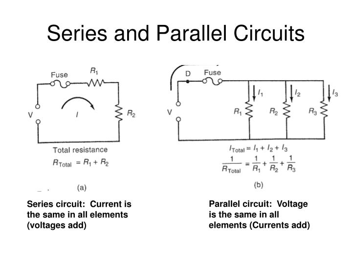
- Current: Remains the same through all components.
- Voltage: The total voltage equals the sum of individual voltage drops.
- Resistance: Add all resistances together for the total resistance.
| Component | Resistance (Ω) | Voltage Drop (V) |
|---|---|---|
| R1 | 10 | 1 |
| R2 | 20 | 2 |
| R3 | 30 | 3 |
| Total | 60 | 6 |

⚠️ Note: Voltages must add up to the supply voltage in series circuits.
Mastering Parallel Circuits

Parallel circuits provide multiple paths for current flow:
- Current: The total current is the sum of currents through each path.
- Voltage: The voltage is the same across each component.
- Resistance: The total resistance is found using the formula for parallel resistance:
- 1/Rtotal = 1/R1 + 1/R2 + … + 1/Rn
An image here can show a simple parallel circuit diagram with current distribution.
Using Simulation Software for Better Understanding

Modern electronics education benefits greatly from simulation tools:
- Circuit Simulation Software: Programs like LTSpice or Multisim allow for detailed analysis.
- Real-time Feedback: See the effect of changing components in real-time.
- Comparison: Simulate both series and parallel circuits side-by-side for comparison.
To summarize, mastering parallel and series circuits involves understanding circuit theory, visualizing circuits, analyzing specific types, and using simulation tools for practical learning. These foundational skills will empower you to tackle more complex circuits and design innovative electronic solutions.
What’s the difference between series and parallel circuits?

+
In a series circuit, components are connected one after the other, so the current is the same throughout. In parallel circuits, components are connected to provide multiple paths for current to flow, allowing each component to have the same voltage drop but different current paths.
How can I calculate total resistance in a parallel circuit?

+
Use the reciprocal sum formula: 1/Rtotal = 1/R1 + 1/R2 + … + 1/Rn. Here, R1, R2 etc. are the resistances of individual resistors.
Why would I use a simulation software?

+
Simulation software provides a safe and cost-effective way to test circuit designs, understand behavior, troubleshoot, and experiment with different configurations without risking hardware damage.