Mastering Electrical Concepts: Answers to Unit 9.3 Worksheet
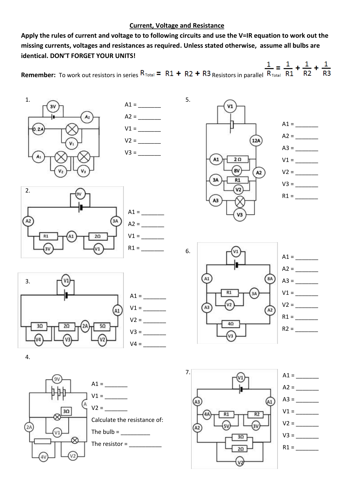
Understanding the intricacies of electrical circuits can often seem daunting, but diving into the fundamental concepts with hands-on activities, like those found in Unit 9.3, is a fantastic way to solidify this knowledge. This post will take you through an in-depth exploration of the key points covered in the worksheet, offering insights, explanations, and tips for mastering these essential electrical concepts.
Understanding Ohm's Law
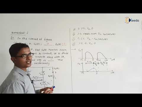

At the heart of electrical theory lies Ohm's Law, which states that the current passing through a conductor between two points is directly proportional to the voltage across the two points. It's a straightforward relationship:
- V (Voltage) = I (Current) * R (Resistance)
Here's how you can practically apply Ohm's Law:
- If you know the voltage and current in a circuit, you can calculate the resistance.
- If you adjust the voltage, the current will change proportionally, assuming resistance remains constant.
Let's delve into an example from the worksheet:
| Voltage (V) | Current (I) | Resistance (R) |
|---|---|---|
| 12V | 3A | 4Ω |

To find the resistance, we use the formula:
- R = V/I = 12V / 3A = 4Ω
⚠️ Note: When using Ohm's Law in real-world applications, consider factors like temperature, which can affect the resistance of materials, especially metals.
Series and Parallel Circuits

Understanding how components are connected in a circuit is crucial for electrical engineering. Here's a brief overview:
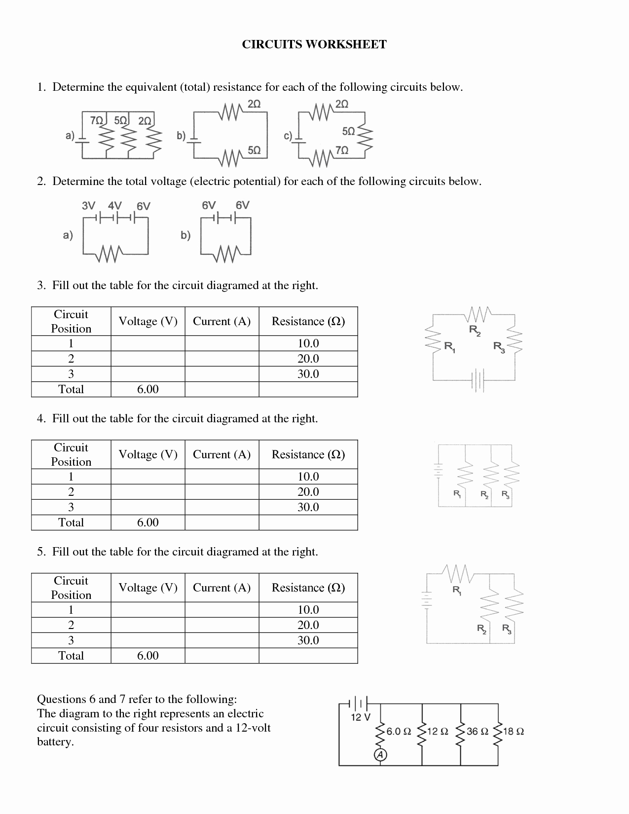
- Series Circuit: Components are connected sequentially. The same current flows through all components, but the voltage drops across each component.
- Parallel Circuit: Components are connected side by side. The voltage across each is the same, but the total current splits among the branches.
Calculating Total Resistance in Series

In a series circuit, to find the total resistance (R_T):
- R_T = R_1 + R_2 + ... + R_n
Calculating Total Resistance in Parallel

In parallel circuits, the formula for total resistance (R_T) is:
- 1/R_T = 1/R_1 + 1/R_2 + ... + 1/R_n
The Power Formula
Power (P) in an electrical circuit can be calculated with:
- P = V * I
Worksheet problems often ask you to determine power consumption or dissipation:
If a 60W light bulb operates at 120V, what current does it draw?
- I = P/V = 60W/120V = 0.5A
Voltage Divider

The voltage divider is a simple way to produce a lower voltage from a higher voltage source. Here's how it works:
- Divide the voltage across a series of resistors, where the voltage across each resistor is proportional to its resistance.
Wrap-Up
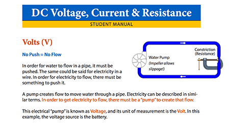
By completing the Unit 9.3 worksheet, you've gained a deeper understanding of fundamental electrical concepts. These principles—resistance, voltage, current, power, and how circuits are configured—are not only the foundation for more advanced topics in electronics but are also essential for practical applications in everyday life. They allow you to make sense of how electrical devices work, troubleshoot problems, and design circuits with specific functionalities. Keep practicing these concepts, and you'll find that electrical engineering becomes not just understandable but fascinating.
What is Ohm’s Law?

+
Ohm’s Law states that the current through a conductor between two points is directly proportional to the voltage across the two points. It’s expressed as V = I * R, where V is voltage, I is current, and R is resistance.
Why does resistance change in series and parallel circuits?
+
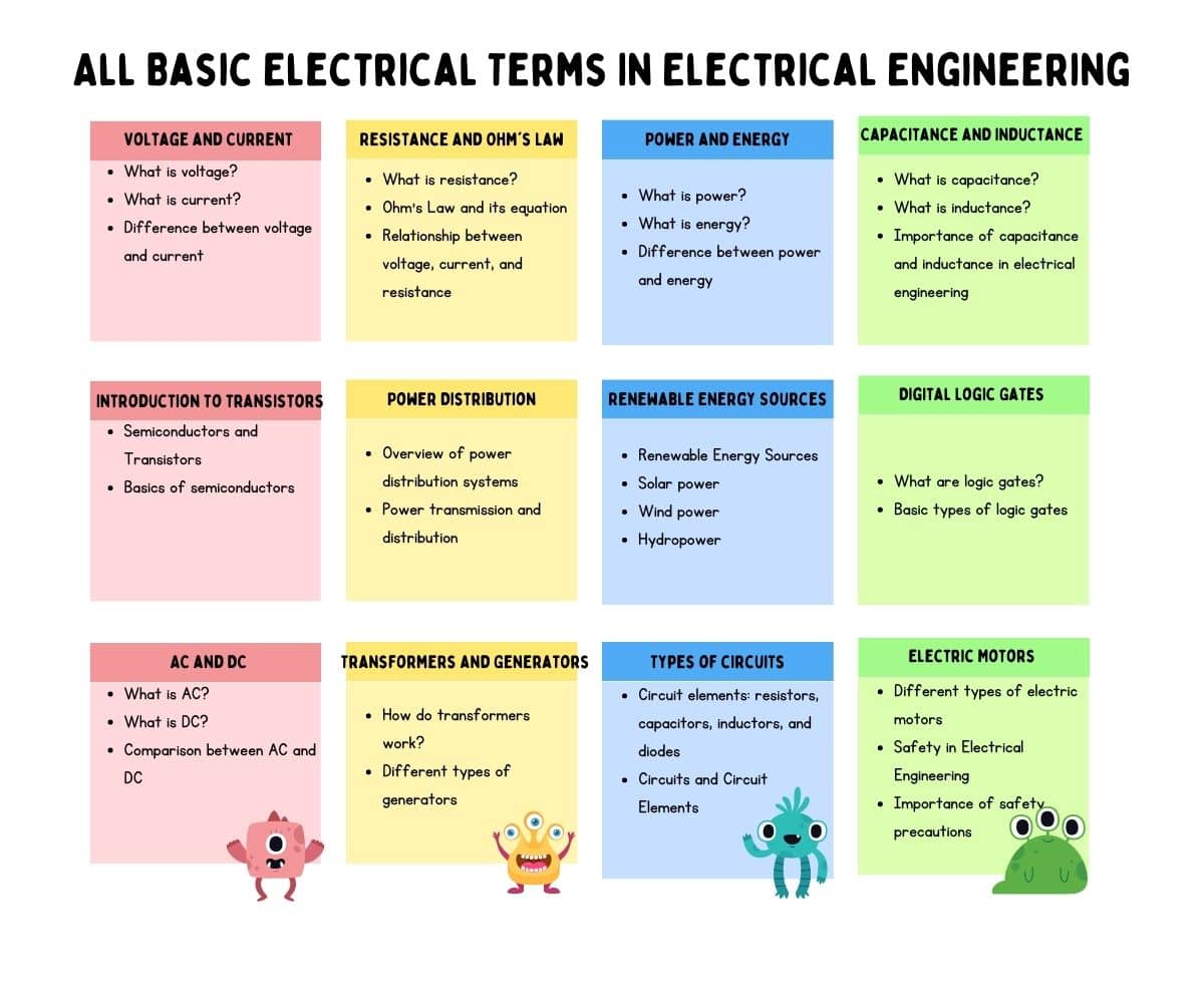
In a series circuit, resistance increases because the current has to travel through each resistor sequentially. In contrast, in parallel circuits, resistance decreases because the current can flow through multiple pathways, reducing the effective resistance.
What’s the main difference between AC and DC?
+
The primary difference is that AC (Alternating Current) periodically reverses direction, while DC (Direct Current) flows in one constant direction. AC is typically used for power transmission, while DC is often used in electronic circuits and batteries.
How does temperature affect resistance?

+
As temperature increases, the thermal agitation of electrons in a conductor increases, leading to more collisions with atoms, which in turn increases the resistance. However, some materials like semiconductors exhibit negative temperature coefficients where resistance decreases with temperature.
How do you calculate power in an electric circuit?

+
Power in an electrical circuit can be calculated using the formula P = V * I, where P is power, V is voltage, and I is current. Alternatively, it can be calculated as P = I^2 * R or P = (V^2) / R if resistance is known.