5 Essential Circuit Symbols Every DIY Enthusiast Must Know

In the world of electronics, circuit diagrams are the blueprint for creating and understanding circuits. They are crucial for any DIY enthusiast who wants to dabble in electronics, repair devices, or build projects from scratch. Understanding circuit symbols is not just about recognizing these diagrams; it's about translating them into real-life connections, ensuring the circuit functions as intended. Here, we delve into 5 essential circuit symbols that every DIY enthusiast should know, exploring their significance and application in practical scenarios.
1. The Battery Symbol


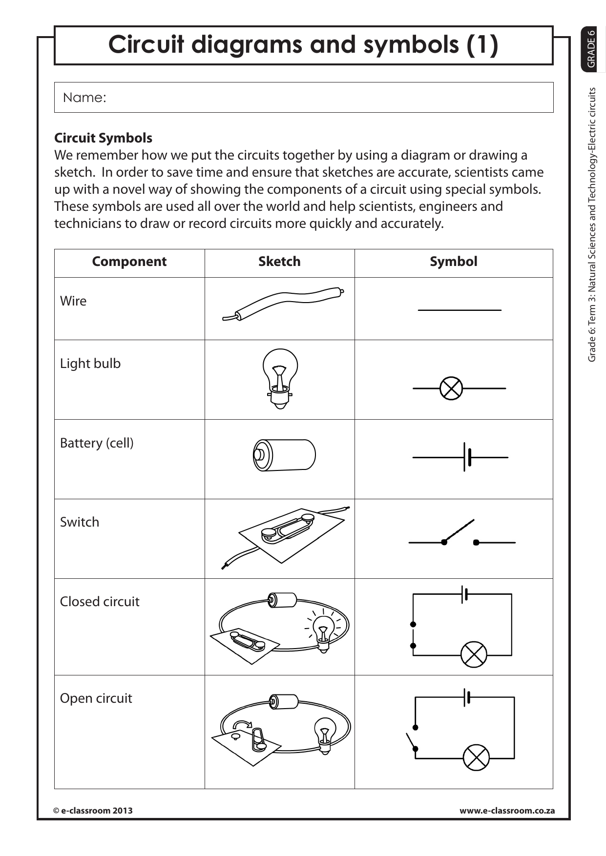
A battery is the power source in many circuits, providing the necessary voltage to energize components. Here's how to identify it:
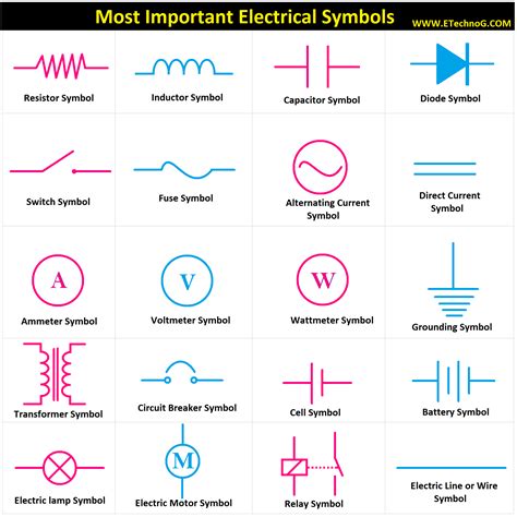
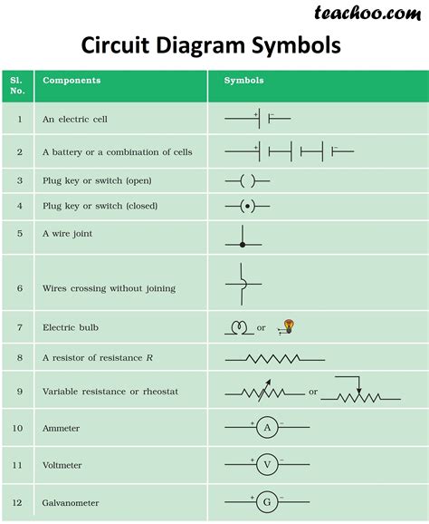
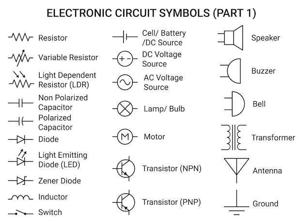
- Parallel lines: A short line and a long line, or two long lines with a space in between.
- + and - signs: Indicate polarity, where the longer line or the '+' sign is positive.
- Multiple cells: For multiple cells, the symbol might include multiple sets of these lines.
The battery symbol tells us not only that there's a power source but also about its capacity and type (single cell, multiple cells, rechargeable).
🔋 Note: When interpreting a circuit diagram, ensure you match the battery type to the circuit's requirements for voltage and current.
2. The Resistor Symbol


Resistors control the flow of current in a circuit by providing resistance. Here’s what you need to know:
- Zigzag or Rectangle: The traditional symbol is a zigzag line, but sometimes a rectangle or a filled block is used.
- Value notation: Resistors often have numbers indicating their value in ohms (Ω).
They're essential for limiting current, dividing voltage, and setting bias in transistor circuits. When selecting resistors:
- Choose the correct resistance value.
- Consider the power rating to prevent overheating.
⚙️ Note: Resistors come with various bands of color for easy identification of their values. Learning these color codes can be very useful.
3. Capacitor Symbol


Capacitors store electric charge and release it when needed, playing a crucial role in:
- Filtering: Smoothing out voltage fluctuations in power supplies.
- Coupling: Allowing signals to pass from one circuit to another without direct current linkage.
- Timing: Controlling charge and discharge rates for timing circuits.
Their symbols vary:
- Two parallel lines: Electrolytic capacitor.
- One curved and one straight line: Polarized electrolytic capacitor.
- Two straight lines with a gap: Non-polarized capacitor.
📝 Note: When dealing with capacitors, ensure correct polarity for polarized types. Mismatching leads to catastrophic failure.
4. Inductor Symbol


Inductors store energy in a magnetic field when current flows through them. Here are their key attributes:
- Coil: Represented as a series of loops or a hollow circle.
- Value indication: Might show inductance in Henrys (H).
Inductors are useful for:
- Filtering: Similar to capacitors, for smoothing current.
- Choke: Blocking AC while allowing DC to pass.
- Transformers: Inducing voltage in another coil through mutual inductance.
⚠️ Note: Like capacitors, inductors have a polarity in some applications. Understanding this is key to preventing circuit damage.
5. Diode Symbol


Diodes are one-way gates for current. Here’s how to read their symbol:
- Triangle: Points towards the direction current flows.
- Vertical line: Indicates the cathode (negative side).
Diodes are essential for:
- Rectification: Converting AC to DC.
- Protection: Preventing reverse current flow.
- Switching: In digital logic, for on/off control.
The basic diode has evolved into many types:
| Type | Symbol Variation |
|---|---|
| Rectifier Diode | Standard Triangle |
| LED | Triangle with Arrows or a Circle |
| Zener Diode | Triangle with Two Lines |

As we conclude our journey through these essential circuit symbols, remember that each symbol is a gateway to understanding how your electronic devices work. From powering your circuits with batteries to controlling current with resistors, each component plays a critical role. These symbols allow DIY enthusiasts to not only decipher circuit diagrams but also to troubleshoot, repair, or innovate with electronic systems. Understanding these symbols is like learning a new language—one that lets you converse with the vast world of electronics.
What is the difference between AC and DC?

+
Alternating Current (AC) changes direction periodically, whereas Direct Current (DC) flows in one direction. AC is used for household electricity, and DC is often generated by batteries or used in electronic devices after rectification.
How do I choose the right resistor for my circuit?

+
Select a resistor by calculating the needed resistance for your circuit. Consider the power rating to ensure it can handle the current without overheating. The color bands on the resistor indicate its value, so understanding these bands is beneficial.
Why would I need an inductor in my circuit?

+
Inductors are used for filtering, blocking AC while passing DC, and in applications like transformers. They store energy in a magnetic field, which can be useful for smoothing current, in signal processing, or in power conversion systems.
What happens if I connect a polarized capacitor the wrong way?

+
Connecting a polarized capacitor with reversed polarity can lead to it exploding, leaking, or failing. Always check the markings on the capacitor to ensure proper polarity connection.
Can I use any diode in a circuit where rectification is needed?

+
While a standard rectifier diode can work for most AC to DC rectification, the choice depends on the circuit’s requirements for voltage, current, and switching speed. Special types like Schottky diodes offer lower forward voltage drops or faster switching for specific applications.


